 es
es English
 中文简体
中文简体 Español


Core Characteristics
Advantages
"1. Significantly improved rigidity and creep resistance: compared to pure PETG, it resists bending and deformation much better, making it suitable for load-bearing structural parts, with minimal dimensional shrinkage/warping and higher printing precision.
2. Matte, frosted surface finish, without PETG's characteristic translucent gloss; electrically insulating and non-conductive, suitable for electrical housings and insulating brackets.
3. Chemical resistance: resistant to alcohol, detergents, and moisture, usable in damp outdoor environments; not prone to brittle cracking at low temperatures (QIDI Tech).
4. Print-friendly: doesn't require a mandatory enclosed chamber, has very low odor, and is much simpler to print than nylon-GF.
5. Better impact resistance than PETG‑CF (carbon fiber): unlike carbon-fiber parts, it doesn't tend to shatter outright on impact — its toughness sits between pure PETG and PETG‑CF."
Disadvantages
1. Highly abrasive: glass fiber quickly wears down brass nozzles, so a hardened steel nozzle is required; 0.2mm fine nozzles are prohibited, ≥0.4mm is recommended (QIDI Tech).
2. Reduced Z-axis interlayer strength: in FDM printing, fibers are laid mainly in the XY plane, so vertical strength is weaker — structural design should avoid heavy loads in the Z direction.
3. Lower elongation at break, more brittle than pure PETG, losing pure PETG's high ductility.
4. Still moisture-absorbing — must be dried before printing, otherwise bubbling, stringing, and poor interlayer bonding will occur."
Reference Printing Parameters (FDM)
| Item | Recommended Parameters |
| Nozzle temperature | 240–270°C, typically 250–260°C |
| Bed temperature | 60–75°C, 65–70°C for PEI sheets |
| Print speed | 40–100 mm/s, 50–70 mm/s recommended for structural parts |
| Fan | 50–100%, PETG ‑ GF requires cooling |
| Drying conditions | 65–70°C, 4–8 hours; 8 hours recommended in humid environments |
| Nozzle spec | Hardened steel nozzle, ≥0.4mm, brass nozzles strictly prohibited |
| Chamber | Not required; an enclosure is recommended in drafty environments to reduce warping |
| Annealing | Holding printed parts at 65–70°C in an oven for 8–12 hours can further improve heat resistance and dimensional stability. |
Typical Applications
"Mechanical fixtures, tooling/jigs, positioning brackets
Load-bearing structural parts for drones, robots, bicycles
Electrical insulating housings, connector bases
Outdoor equipment, moisture-resistant functional parts
As a substitute for ABS‑GF — lower odor and easier to print"
Important Printing Notes
"1. Hardware change is mandatory: use a hardened steel nozzle. A brass nozzle will widen in bore diameter within a short time, ruining precision; don't use a 0.2mm fine nozzle, as it clogs easily.
2. Drying can't be skipped: glass-fiber composite absorbs moisture more readily than standard PETG — if damp, it will bubble, pop, and delaminate between layers; store unused filament sealed in a dry box.
3. Structural design: try to align load-bearing directions with the XY print plane, and minimize impact or tensile loads in the Z direction.
4. Bowden-type printers: the filament becomes brittle, so avoid excessive retraction to prevent the filament from snapping inside the tube; direct-drive printers perform better.
5. Recommended layer height ≥0.2mm — too thin a layer will worsen nozzle wear and cause unstable extrusion."
Product Description
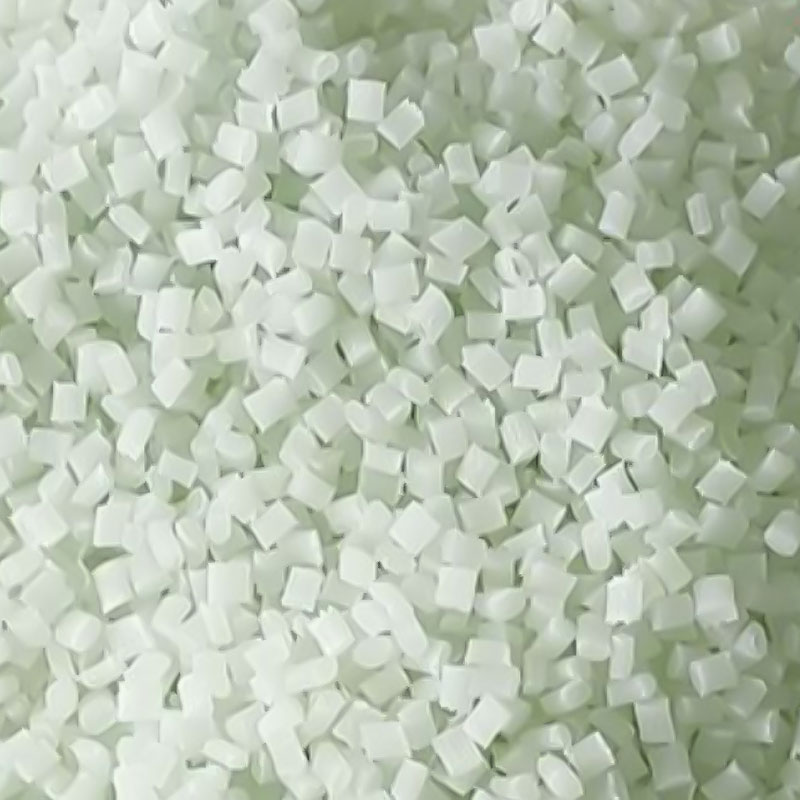
| Resin Identificatio n | 1 0%glass fiber reinforced, food contact grade, chemical resistance, high modulus, high rigidity, high toughness, detergent resistance, disinfectant resistance, transparency, hydrolysis resistance, heat stabi lity, laser weldable | |||||||
| Color | Natural color, Typical color | |||||||
| Main applications | 3D printing, functional prototype, lightweight clamp, fixture, structur al part, engineering component, bracket, robotic arm end effector, tooling fixtur e, durable prototype, precision instrument part, mechanical enclosure | |||||||
| Processing Meth od | Injection Molding | |||||||
| Typical Propertie s | Test Method | Test Condition | Value | Unit | ||||
| Physical Properties | ||||||||
| Density | DIN ENISO 1183 | 23 ℃ | 1.3 | g/cm³ | ||||
| Melt Flow Rate | DIN ENISO 1133 | 270° ℃/ 5kg | 12 | g/10min | ||||
| Shrinkage | GB 1 5585 | 0.15-0.25 | % | |||||
| Mechanical Propertie s | ||||||||
| Tensile Strength | DIN ENISO527 | 50mm/min | 70 | M P a | ||||
| Tensile modulus | 3300 | MPa | ||||||
| Elongation at Break | 5 | % | ||||||
| Flexural Strength | DIN EN ISO 178 | 2mm/min | 105 | MPa | ||||
| Flexural Modulus | 3300 | M P a | ||||||
| Izod Note Impact Strength | DIN EN ISO 180 | 4mm,23℃ | 5 | KJM2 | ||||
| Izod Note Impact Strengt h | DIN EN ISO 180 | 4mm,-30 ℃ | 4 | KJ/M² | ||||
| Izod UN-notched Impact Strength | DIN EN ISO 180 | 4mm,23℃ | 60 | KJ/M² | ||||
| Izod UN-notched Impact Strength | DIN EN ISO 180 | 4mm,-30 ℃ | 45 | K J/ M² | ||||
| Thermal Performance | ||||||||
| Heat Deformation Temperature | DIN ENISO75 | 1.8MPa | 74 | ℃ | ||||
| Heat Deformation Temperature | DIN EN ISO75 | 0.45MPa | 80 | ℃ | ||||
| melting emperature | 259-271 | ℃ | ||||||
| Flame retardant propertie s | ||||||||
| Flame retardant properties | UL94 | 0.75mm | HB | |||||
| Flame retardant propeties | UL94 | 1.5mm | HB | |||||
| Flame retardant properties | UL94 | 3 mm | HB | |||||
| GWEIGow wire flammability inde | IEC60695-2-12 | 0.75mm | 550 | ℃ | ||||
| (GWFI)Glow wie flammability index | IEC60695-2-12 | 1.5mm | 550 | ℃ | ||||
| (GWEIDGlo weflamabity nde | IEC60695-2-12 | 3 mm | 650 | ℃ | ||||
| (GWFI)Glow wie flammability index | IEC60695-2-13 | 0.75mm | 550 | ℃ | ||||
| (GWEIDGlo weflamabity nde | IEC60695-2-13 | 1.5mm | 550 | ℃ | ||||
| (GWELDclow wie famabity nde | IEC60695-2-13 | 3 mm | 550 | ℃ | ||||
| IOptical Properties | ||||||||
| Haze | ASTM D1003 | 48 | % | |||||
| Transmittan ce | ASTM D1003 | 83 | % | |||||
| Electical Properti es | ||||||||
| urface Resistivity | ASTM D257 | 1.24E 16 | Q | |||||
| Volume Resistivity | ASTM D257 | 3.34E 16 | Ω ·cm | |||||
| Dielectric Strength(short time,2000V/sec) | ASTM D149 | 15.13 | kV/mm | |||||
| Dielectric Constant 1 kHz | ASTM D150 | 3.49 | ||||||
| Dielectric Constant 1 MHz | ASTM D150 | 3.22 | ||||||
| Dissipation Factor 1 kHz | ASTM D150 | 0.0064 | ||||||
| Dissipation Factor 1 MHz | ASTM D150 | 0.0252 | ||||||
Plastic Drying
| Drying Time | 4~6hr |
| Drying Temperature | 60~70℃ |
| Drying Equipment | Hot air dryer |
| Drying Type | Continuous drying(production process) |
| Injection Molding Process | |
| Nzle Section | 270~290℃ |
| Plastics Section | 280~320℃ |
| Conveying Section | 260~280°℃ |
| Maximum Injection Temperature | 330℃ |
| I njection Pressure | 40~120MPa |
| Injection Speed | 30~75mm/s |
| Plasticization Pressure Velocity | 65~100MPa,60~85mm/s |
| Plasticization Back Pressure | 10~40MPa |
| Recommended Mold Temperature | 90~120℃ |
| Recommended 3D printing processing technology for this engineering plastic | |
| Plastic Drying | |
| Drying Time | 4~6hr |
| Drying Temperature | 65~70°C |
| Drying Equipment | Hot air dryer |
| Drying Type | Continuous drying (production process) |
| 3D forming process | |
| nozzle section | 250~270°C |
| Heated bed temperature | 75~85℃ |
| print speed | 40-60mm/s |
| travel speed | 100-150mm/s |
| layer height | 0.2-0.3mm |
| line width | 100%-120% |
| fan speed | 30%-050% |
| retraction distance | Direct drive extruder: 3- 6 mm; Bowden extruder: 4- 7 mm |
| retraction speed | 40-60 |